Content Menu
● Understanding SMT PCB Symbols
>> Why SMT PCB Symbols Matter
● Key Components Represented by SMT PCB Symbols
>> 1. Resistors (R)
>> 2. Capacitors (C)
>> 3. Inductors (L)
>> 4. Diodes (D)
>> 5. Transistors (Q)
>> 6. Integrated Circuits (U)
>> 7. Connectors and Switches (J, S)
>> 8. Other Components
● How SMT PCB Symbols Are Structured
>> Reference Designators
>> Symbol Details
● Common SMT PCB Symbol Examples
>> Resistor Symbol
>> Capacitor Symbol
>> Diode Symbol
>> Transistor Symbol
>> Integrated Circuit Symbol
● Importance of SMT PCB Symbols in Design and Manufacturing
● Conclusion
● Frequently Asked Questions (FAQ)
>> 1. What do SMT PCB symbols represent?
>> 2. How are SMT components labeled in PCB symbols?
>> 3. What are the common SMT component types shown in PCB symbols?
>> 4. Why is polarity important in SMT PCB symbols?
>> 5. How do SMT PCB symbols aid automated assembly?
● Citations:
Surface Mount Technology (SMT) has revolutionized the electronics manufacturing industry by enabling compact, efficient, and high-density printed circuit boards (PCBs). At the heart of SMT PCB design and assembly lie SMT PCB symbols, which are graphical representations of electronic components used in schematic diagrams and PCB layouts. Understanding these symbols and their key components is essential for engineers, designers, and technicians working with SMT PCBs.

This comprehensive article explores the key components in SMT PCB symbols, detailing their types, functions, and significance in PCB design. We will also discuss common SMT components, their symbolic representations, and how these symbols facilitate effective communication in the PCB design and manufacturing process.
Understanding SMT PCB Symbols
SMT PCB symbols are standardized graphical icons that represent various surface mount devices (SMDs) on circuit diagrams and PCB layouts. These symbols help engineers visualize how components are interconnected and ensure accurate placement during assembly.
Why SMT PCB Symbols Matter
- Clarity in Design: Symbols provide a clear and concise way to represent complex components.
- Standardization: They follow industry standards, making designs universally understandable.
- Efficient Assembly: Accurate symbols guide automated placement machines and technicians.
- Troubleshooting: Symbols help in identifying components quickly during testing and repair.
Key Components Represented by SMT PCB Symbols
SMT PCB symbols cover a variety of electronic components, each with unique functions and characteristics. Below are the primary categories and their symbolic representations.
1. Resistors (R)
- Symbol: Usually denoted by the letter "R" followed by a number (e.g., R1, R15).
- Function: Resist the flow of electrical current; used for current limiting, voltage division, biasing, filtering, and impedance matching.
- Types: Thick film, thin film, metal film resistors.
- Marking: Can be represented by three-figure or four-figure coding schemes on the physical component.
- SMT Packages: Common sizes include 0402, 0603, 0805, 1206, 2512, etc.[3][4]
2. Capacitors (C)
- Symbol: Denoted by "C" followed by a number (e.g., C1, C10).
- Function: Store electrical energy in an electric field; used for filtering, decoupling, and energy storage.
- Types: Ceramic (Class 1 and Class 2), tantalum, electrolytic capacitors.
- SMT Packages: Similar to resistors, capacitors come in sizes like 0402, 0603, 0805, and 1206.
- Material Considerations: Capacitance tolerance and Equivalent Series Resistance (ESR) are critical parameters.[3][4][7]
3. Inductors (L)
- Symbol: Represented by "L" plus a number (e.g., L1, L5).
- Function: Store energy in a magnetic field; used for filtering, signal tuning, and impedance matching.
- Types: Wirewound, multilayer inductors.
- Materials: Ferrite and ceramic cores influence inductance and losses.
- SMT Packages: Similar size ranges as resistors and capacitors.[3][7]
4. Diodes (D)
- Symbol: Marked as "D" or "CR" with a number (e.g., D1, D3).
- Function: Allow current flow in one direction; includes types such as LED, Zener, crystal diodes.
- Variants: Zener diodes, varactor diodes, and photodiodes.
- SMT Packages: Various small form factors designed for surface mounting.[1][3]
5. Transistors (Q)
- Symbol: Denoted by "Q" plus a number (e.g., Q1, Q2).
- Function: Act as amplifiers or switches.
- Types: Bipolar junction transistors (BJTs), field-effect transistors (FETs).
- SMT Packages: SOIC, QFN, TSSOP, and others.
- Pin Identification: Symbols include pin-1 indicators and orientation marks.[3][5][7]
6. Integrated Circuits (U)
- Symbol: Denoted by "U" with a number (e.g., U1).
- Function: Complex components combining multiple circuits; microcontrollers, amplifiers, memory chips.
- SMT Packages: SOIC, QFN, BGA, QFP, TSSOP.
- Characteristics: Multiple pins/pads, thermal considerations, and power dissipation are important.[4][7][10]
7. Connectors and Switches (J, S)
- Connectors: Marked as "J" (e.g., J1), used for interfacing PCBs with external devices.
- Switches: Marked as "S" (e.g., S1), include buttons and toggle switches.
- Function: Provide mechanical and electrical connections.
- SMT Packages: Designed for surface mounting with appropriate mechanical strength.[1][4]
8. Other Components
- Oscillators (G): Provide clock signals.
- Relays (K): Electrically operated switches.
- Test Points (TP): Marked for testing and troubleshooting.
- Fuses (F): Provide circuit protection.
- Transformers (T): Used for voltage transformation and isolation.[1][5][9]

How SMT PCB Symbols Are Structured
Reference Designators
Each SMT component symbol includes a reference designator, a letter-number code that uniquely identifies the component on the PCB. Examples include:
| Letter | Component Type |
| R | Resistor |
| C | Capacitor |
| L | Inductor |
| D, CR | Diode |
| Q | Transistor |
| U | Integrated Circuit |
| J | Connector |
| S | Switch |
| F | Fuse |
| T | Transformer |
| TP | Test Point |
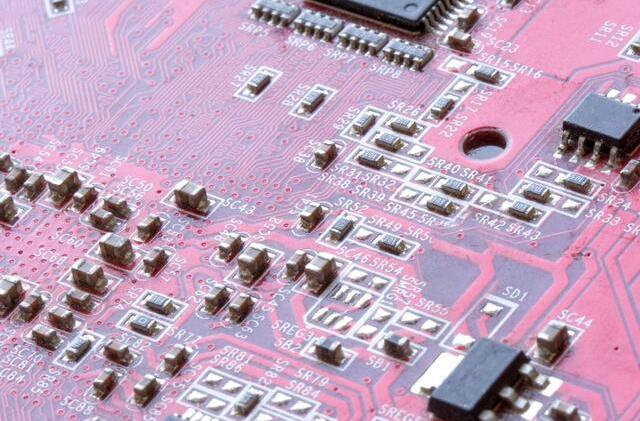
These designators are printed on the PCB silkscreen layer to assist in assembly and troubleshooting.[1][5][9]
Symbol Details
- Pin Numbers: Indicate connection points.
- Polarity Marks: For polarized components like diodes and electrolytic capacitors.
- Package Outline: Sometimes shown to indicate component size and orientation.
- Functional Indicators: Such as transistor type (NPN, PNP) or diode direction.
Common SMT PCB Symbol Examples
Resistor Symbol
A simple zigzag or rectangular shape with two terminals, labeled with "R" and a number.
Capacitor Symbol
Two parallel lines (for non-polarized) or one straight and one curved line (for polarized), labeled with "C".
Diode Symbol
A triangle pointing to a line, indicating the direction of current flow, labeled with "D".
Transistor Symbol
Three-terminal device symbol with arrows indicating current flow, labeled with "Q".
Integrated Circuit Symbol
A rectangle with multiple pins on sides, labeled with "U".
Importance of SMT PCB Symbols in Design and Manufacturing
- Design Accuracy: Ensures correct component placement and orientation.
- Automated Assembly: Pick-and-place machines rely on accurate symbols and footprints.
- Documentation: Facilitates clear communication among engineers, manufacturers, and quality control.
- Troubleshooting: Simplifies fault diagnosis and repair by identifying components quickly.
Conclusion
SMT PCB symbols are fundamental elements in the design, assembly, and maintenance of modern printed circuit boards. They represent a wide range of components—from resistors and capacitors to complex integrated circuits—using standardized graphical icons and reference designators. Understanding these symbols and their key components is essential for anyone involved in PCB design or manufacturing, ensuring precision, efficiency, and reliability in electronic device production.

Frequently Asked Questions (FAQ)
1. What do SMT PCB symbols represent?
SMT PCB symbols represent surface mount electronic components graphically on circuit diagrams and PCB layouts, helping to identify component types, values, and orientations for design and assembly.[3][5]
2. How are SMT components labeled in PCB symbols?
Each SMT component is labeled with a reference designator consisting of a letter (indicating component type) and a number (unique identifier), such as R1 for resistor or U2 for integrated circuit.[1][5]
3. What are the common SMT component types shown in PCB symbols?
Common SMT components include resistors (R), capacitors (C), inductors (L), diodes (D), transistors (Q), integrated circuits (U), connectors (J), and switches (S).[1][4][7]
4. Why is polarity important in SMT PCB symbols?
Polarity indicates the correct orientation for polarized components like diodes and electrolytic capacitors, which is critical for circuit functionality and preventing damage.[3][7]
5. How do SMT PCB symbols aid automated assembly?
They provide precise information on component type, position, and orientation, enabling pick-and-place machines to accurately place components on PCBs during manufacturing.[7]
Citations:
[1] https://jhdpcb.com/blog/fully-understand-pcb-components/
[2] https://pcbdesignworld.com/article/basic-electronic-component-symbols-that-every-pcb-design-engineer-should-know
[3] https://www.qhsmt.com/2023/07/06/smt-line-equipment-electrical-symbols-for-electronic-components/
[4] https://www.pcbonline.com/blog/pcb-smt-components.html
[5] https://www.ultralibrarian.com/2021/05/25/common-pcb-component-codes-to-know-ulc
[6] https://www.pcbway.com/project/shareproject/PCBWay_PCB_Coaster_SMT_Footprint_Reference_Guide_board.html
[7] https://www.anypcba.com/blogs/pcb-assembly-knowledge/the-ultimate-guide-to-pcb-smt-technology-process-applications.html
[8] https://blog.sina.com.cn/s/blog_ab8d958801017uy1.html
[9] https://resources.pcb.cadence.com/blog/2023-identifying-electronic-components-on-a-circuit-board
[10] https://www.pcbonline.com/blog/smd-electronic-components.html
[11] https://patents.google.com/patent/CN102484330A/zh
[12] https://baike.baidu.com/item/%E7%94%B5%E5%AD%90%E7%BB%84%E8%A3%85%E6%8A%80%E6%9C%AF%E4%B8%93%E4%B8%9A%E8%8B%B1%E8%AF%AD/12086345


