Content Menu
● Introduction to SMD Markings
● Common SMD Markings
>> Resistor Markings
>> Capacitor Markings
>> Diode Markings
>> Transistor Markings
>> Integrated Circuit (IC) Markings
● How to Decode SMD Markings
>> Step 1: Identify the Component Type
>> Step 2: Read the Markings
>> Step 3: Use an SMD Markings Decoder
>> Step 4: Cross-Reference with Datasheets
● Importance of SMD Markings
● Conclusion
● FAQ
>> 1. What is an SMD markings decoder?
>> 2. How can I read SMD markings?
>> 3. Why are SMD markings important?
>> 4. Can I find SMD markings online?
>> 5. What should I do if I can't decode SMD markings?
Surface Mount Devices (SMDs) have become a cornerstone of modern electronics, enabling compact designs and efficient manufacturing processes. Understanding SMD markings is crucial for anyone involved in electronics, from hobbyists to professional engineers. This article will delve into the common SMD markings, their meanings, and how to decode them using an SMD markings decoder.

Introduction to SMD Markings
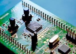
SMDs are components that are mounted directly onto the surface of printed circuit boards (PCBs). Unlike traditional through-hole components, SMDs are smaller and can be placed more densely on a PCB. This miniaturization has led to the widespread use of SMDs in various applications, including smartphones, computers, and automotive electronics.
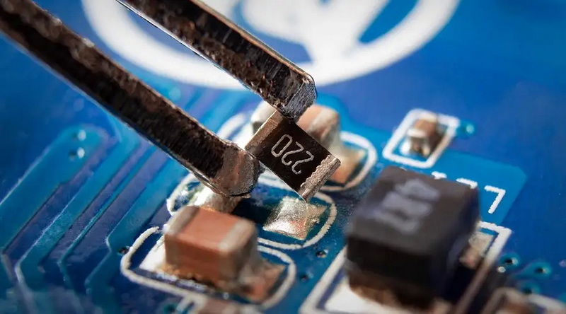
SMD markings are essential for identifying the specifications and characteristics of these components. They typically consist of alphanumeric codes that provide information about the component's value, tolerance, and manufacturer. Understanding these markings is vital for selecting the right components for a project and ensuring proper functionality.
Common SMD Markings
Resistor Markings
Resistors are one of the most common SMD components. The markings on SMD resistors usually indicate their resistance value and tolerance. The most common formats include:
- Three-Digit Code: This code consists of three digits, where the first two digits represent significant figures, and the third digit indicates the multiplier. For example, a marking of "103" would mean 10 followed by three zeros, or 10,000 ohms (10kΩ).
- EIA-96 Code: This is a standardized code used for surface mount resistors. It consists of a letter followed by a number, where the letter indicates the series and the number indicates the resistance value. For example, "R0603" indicates a resistor in the 0603 package size.
Capacitor Markings
Capacitors also have specific markings that indicate their capacitance value and voltage rating. Common formats include:
- Alphanumeric Code: Similar to resistors, capacitors may use a three-digit code to indicate capacitance. For example, "104" indicates a capacitance of 100,000 picofarads (100nF).
- Voltage Rating: Capacitors often have a voltage rating marked on them, which is crucial for ensuring they are used within their safe operating limits. This is typically indicated in volts (V).
Diode Markings
Diodes are another essential component in electronic circuits. Their markings usually indicate the type of diode and its specifications. Common markings include:
- Part Number: Many diodes have a part number printed on them, which can be used to look up their specifications in a datasheet. For example, a diode marked "1N4148" is a standard switching diode.
- Polarity Indicators: Some diodes, especially surface mount Schottky diodes, may have a marking that indicates the anode and cathode. This is crucial for proper installation in a circuit.
Transistor Markings
Transistors are vital for amplification and switching applications. Their markings typically include:
- Part Number: Similar to diodes, transistors have part numbers that can be referenced for detailed specifications. For example, "BC547" is a common NPN transistor.
- Gain Rating: Some transistors may also have a gain rating (hFE) marked on them, which indicates their amplification capability.
Integrated Circuit (IC) Markings
Integrated circuits are complex components that can contain multiple functions. Their markings can be more intricate, often including:
- Part Number: The part number is essential for identifying the IC and its functionality. For example, "LM358" indicates a dual operational amplifier.
- Date Code: Many ICs have a date code that indicates when they were manufactured. This is important for tracking the lifecycle of components in a design.

How to Decode SMD Markings
Decoding SMD markings can be challenging, especially for those new to electronics. However, using an SMD markings decoder can simplify this process significantly. Here are some steps to effectively decode SMD markings:
Step 1: Identify the Component Type
The first step in decoding SMD markings is to identify the type of component you are dealing with. Is it a resistor, capacitor, diode, transistor, or IC? Each type has its own marking conventions.
Step 2: Read the Markings
Carefully examine the markings on the component. Use a magnifying glass if necessary, as SMD markings can be quite small. Write down the alphanumeric codes you see.
Step 3: Use an SMD Markings Decoder
An SMD markings decoder is a tool or software that can help you interpret the markings. Many online resources and mobile apps are available that allow you to input the markings and receive detailed information about the component.
Step 4: Cross-Reference with Datasheets
Once you have decoded the markings, it's a good practice to cross-reference the information with the manufacturer's datasheet. This ensures that you have the correct specifications and can verify the component's suitability for your application.
Importance of SMD Markings
Understanding SMD markings is crucial for several reasons:
- Component Identification: SMD markings allow engineers and technicians to quickly identify components, which is essential for troubleshooting and repairs.
- Design Accuracy: Accurate identification of components ensures that designs are implemented correctly, reducing the risk of errors in manufacturing.
- Quality Control: In manufacturing, SMD markings help maintain quality control by ensuring that the correct components are used in production.
- Inventory Management: For businesses, understanding SMD markings aids in inventory management, ensuring that the right components are stocked and available for production.
Conclusion
In conclusion, SMD markings play a vital role in the world of electronics. They provide essential information about the components used in various applications, from simple resistors to complex integrated circuits. By understanding these markings and utilizing tools like SMD markings decoders, engineers and hobbyists can ensure that they select the right components for their projects, leading to successful designs and implementations.
As technology continues to advance, the importance of SMDs and their markings will only grow. Staying informed about these components and their specifications is crucial for anyone involved in electronics.

FAQ
1. What is an SMD markings decoder?
An SMD markings decoder is a tool or software that helps interpret the alphanumeric codes found on surface mount devices, providing information about the component's specifications.
2. How can I read SMD markings?
To read SMD markings, carefully examine the component using a magnifying glass if necessary. Write down the alphanumeric codes and use an SMD markings decoder to interpret them.
3. Why are SMD markings important?
SMD markings are important for identifying components, ensuring design accuracy, maintaining quality control, and managing inventory in electronics manufacturing.
4. Can I find SMD markings online?
Yes, many online resources and databases provide information about SMD markings, including decoding tools and manufacturer datasheets.
5. What should I do if I can't decode SMD markings?
If you cannot decode SMD markings, consider using an SMD markings decoder tool or consulting with a knowledgeable colleague or online community for assistance.


