Content Menu
● Understanding SMT PCB Assembly
● Factors Influencing Soldering Method Selection
>> 1. Component Types and Sizes
>> 2. PCB Complexity
>> 3. Production Volume
>> 4. Quality Requirements
>> 5. Environmental Considerations
● Common Soldering Methods for SMT PCB Assembly
>> 1. Reflow Soldering
>> 2. Wave Soldering
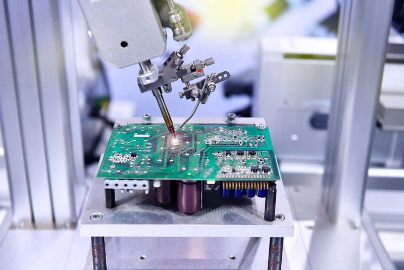
>> 3. Selective Soldering
>> 4. Vapor Phase Soldering
>> 5. Manual Soldering
● Choosing the Right Soldering Method
>> 1. Analyze your PCB design:
>> 2. Evaluate your production requirements:
>> 3. Consider your resources:
>> 4. Assess environmental factors:
>> 5. Consult with experts:
● Best Practices for Successful SMT Soldering
>> 1. Use high-quality solder paste and flux:
>> 2. Optimize your PCB design for SMT assembly:
>> 3. Implement proper process controls:
>> 4. Perform regular equipment maintenance:
>> 5. Train operators and technicians:
>> 6. Implement thorough inspection and testing procedures:
● Emerging Trends in SMT Soldering
>> 1. Lead-free soldering:
>> 2. Miniaturization:
>> 3. Advanced thermal management:
>> 4. Automation and Industry 4.0:
>> 5. Green manufacturing:
● Conclusion
● FAQ
>> 1. What is the difference between SMT and through-hole soldering?
>> 2. How do I choose between reflow and wave soldering for my SMT PCB assembly?
>> 3. What are the key considerations for implementing lead-free soldering in SMT PCB assembly?
>> 4. How can I improve the quality of solder joints in SMT PCB assembly?
>> 5. What are the challenges of soldering fine-pitch components in SMT PCB assembly?
● Citations:
Surface Mount Technology (SMT) has revolutionized the electronics manufacturing industry, enabling the production of smaller, more complex, and more efficient printed circuit boards (PCBs). A crucial aspect of SMT PCB assembly is the soldering process, which creates the electrical and mechanical connections between components and the board. Choosing the right soldering method is essential for ensuring the quality, reliability, and efficiency of your PCB assembly. This article will guide you through the various soldering methods available for SMT PCB assembly and help you make an informed decision based on your specific requirements.

Understanding SMT PCB Assembly
Before delving into the soldering methods, it's important to understand the basics of SMT PCB assembly. SMT involves mounting components directly onto the surface of the PCB, as opposed to through-hole technology where component leads are inserted through holes in the board[1]. This approach offers several advantages, including:
- Higher component density
- Smaller and lighter PCBs
- Improved electrical performance
- Faster and more automated assembly process
The SMT assembly process typically involves the following steps:
1. Solder paste application
2. Component placement
3. Reflow soldering
4. Inspection and testing
Factors Influencing Soldering Method Selection
When choosing a soldering method for SMT PCB assembly, several factors need to be considered:
1. Component Types and Sizes
The types and sizes of components used in your PCB design play a significant role in determining the appropriate soldering method. Some components may require specific soldering techniques due to their size, shape, or thermal sensitivity.
2. PCB Complexity
The complexity of your PCB design, including the number of layers, component density, and presence of mixed technologies (e.g., SMT and through-hole), can influence the choice of soldering method.
3. Production Volume
The volume of PCBs you need to produce will impact your soldering method selection. Some methods are more suitable for high-volume production, while others may be more cost-effective for low-volume or prototype runs.
4. Quality Requirements
Different applications may have varying quality requirements. For instance, aerospace or medical devices may require higher reliability standards, which can influence the choice of soldering method.
5. Environmental Considerations
Environmental factors, such as the operating temperature range of the final product and exposure to humidity or vibration, can affect the choice of soldering method and materials.
Common Soldering Methods for SMT PCB Assembly
Now, let's explore the most common soldering methods used in SMT PCB assembly:
1. Reflow Soldering
Reflow soldering is the most widely used method for SMT PCB assembly. This process involves the following steps:
1. Applying solder paste to the PCB pads using a stencil
2. Placing components onto the solder paste deposits
3. Passing the PCB through a reflow oven, where the solder paste melts and forms solder joints
Advantages of Reflow Soldering:
- High throughput and efficiency
- Suitable for high-density boards
- Excellent solder joint quality
- Easily automated process
Disadvantages of Reflow Soldering:
- Initial equipment cost can be high
- Requires careful temperature profiling
- May not be suitable for some heat-sensitive components
2. Wave Soldering
While primarily used for through-hole components, wave soldering can also be applied to SMT components in certain situations. The process involves:
1. Applying adhesive to hold SMT components in place
2. Placing components on the PCB
3. Passing the PCB over a wave of molten solder
Advantages of Wave Soldering:
- Can handle both SMT and through-hole components
- Suitable for high-volume production
- Cost-effective for boards with a mix of SMT and through-hole components
Disadvantages of Wave Soldering:
- Limited suitability for fine-pitch SMT components
- Higher risk of thermal stress on components
- May require special fixtures or pallets
3. Selective Soldering
Selective soldering is a more targeted approach, ideal for mixed-technology boards or when certain areas of the PCB require specific soldering attention. The process involves:
1. Applying flux to specific areas
2. Selectively applying molten solder to those areas using a miniature solder wave or a laser
Advantages of Selective Soldering:
- Precise control over solder application
- Suitable for heat-sensitive components
- Can handle complex board layouts
Disadvantages of Selective Soldering:
- Slower than reflow or wave soldering
- Higher equipment cost
- May require programming for each board design
4. Vapor Phase Soldering
Vapor phase soldering, also known as condensation soldering, uses the latent heat of vaporization to heat the PCB and melt the solder. The process involves:
1. Applying solder paste and placing components
2. Suspending the PCB in a chamber filled with vapor of a special heat transfer liquid
3. The vapor condenses on the cooler PCB, transferring heat and melting the solder
Advantages of Vapor Phase Soldering:
- Uniform heating across the entire PCB
- Reduced risk of overheating components
- Suitable for high-density and multi-layer boards
Disadvantages of Vapor Phase Soldering:
- Higher initial equipment cost
- Requires special heat transfer liquids
- May not be suitable for all component types
5. Manual Soldering
While not typically used for high-volume production, manual soldering still has its place in SMT PCB assembly, particularly for prototyping, rework, or low-volume production. This method involves:
1. Applying solder paste manually or using a dispenser
2. Placing components by hand
3. Using a soldering iron to create solder joints
Advantages of Manual Soldering:
- Low initial equipment cost
- Flexibility for prototyping and small-scale production
- Suitable for rework and repair
Disadvantages of Manual Soldering:
- Time-consuming and labor-intensive
- Inconsistent quality dependent on operator skill
- Not suitable for high-volume production or fine-pitch components

Choosing the Right Soldering Method
To select the most appropriate soldering method for your SMT PCB assembly, consider the following steps:
1. Analyze your PCB design:
- Component types and sizes
- Board complexity and density
- Mixed technology requirements
2. Evaluate your production requirements:
- Volume of production
- Turnaround time
- Quality standards
3. Consider your resources:
- Available equipment and budget
- Operator skill level
- Space constraints
4. Assess environmental factors:
- Operating temperature range
- Exposure to humidity or vibration
- Regulatory requirements
5. Consult with experts:
- PCB assembly service providers
- Component manufacturers
- Industry peers
By carefully considering these factors, you can make an informed decision on the most suitable soldering method for your SMT PCB assembly needs.
Best Practices for Successful SMT Soldering
Regardless of the soldering method you choose, following these best practices will help ensure successful SMT PCB assembly:
1. Use high-quality solder paste and flux:
- Choose materials compatible with your components and PCB substrate
- Ensure proper storage and handling of solder paste
2. Optimize your PCB design for SMT assembly:
- Follow design for manufacturability (DFM) guidelines
- Consider thermal management in your layout
3. Implement proper process controls:
- Monitor and control temperature profiles
- Maintain clean and controlled assembly environment
4. Perform regular equipment maintenance:
- Calibrate and clean soldering equipment regularly
- Replace worn parts as needed
5. Train operators and technicians:
- Ensure proper understanding of SMT soldering techniques
- Provide ongoing training on new technologies and methods
6. Implement thorough inspection and testing procedures:
- Use automated optical inspection (AOI) systems
- Perform X-ray inspection for hidden solder joints
- Conduct functional testing of assembled PCBs
By adhering to these best practices, you can maximize the effectiveness of your chosen soldering method and produce high-quality SMT PCB assemblies consistently.
Emerging Trends in SMT Soldering
As technology continues to advance, new trends are emerging in SMT soldering techniques:
1. Lead-free soldering:
- Driven by environmental regulations
- Requires different temperature profiles and material considerations
2. Miniaturization:
- Increasing demand for smaller components and finer pitch
- Challenges traditional soldering methods
3. Advanced thermal management:
- Development of new solder alloys with improved thermal properties
- Integration of thermal management solutions in PCB design
4. Automation and Industry 4.0:
- Increased use of robotics and artificial intelligence in soldering processes
- Real-time monitoring and adjustment of soldering parameters
5. Green manufacturing:
- Focus on energy-efficient soldering processes
- Development of eco-friendly flux and cleaning solutions
Staying informed about these trends can help you make future-proof decisions when selecting soldering methods for your SMT PCB assembly projects.
Conclusion
Choosing the right soldering method for SMT PCB assembly is crucial for ensuring the quality, reliability, and efficiency of your electronic products. By understanding the various soldering techniques available, considering the factors that influence method selection, and following best practices, you can optimize your SMT PCB assembly process.
Remember that the best soldering method may vary depending on your specific project requirements, production volume, and available resources. It's essential to continually evaluate your soldering processes and stay informed about emerging trends to maintain a competitive edge in the rapidly evolving electronics manufacturing industry.

FAQ
1. What is the difference between SMT and through-hole soldering?
SMT (Surface Mount Technology) involves soldering components directly onto the surface of the PCB, while through-hole soldering requires component leads to be inserted through holes in the board. SMT allows for higher component density, smaller PCB sizes, and faster assembly processes, making it the preferred method for modern electronics manufacturing.
2. How do I choose between reflow and wave soldering for my SMT PCB assembly?
Reflow soldering is generally preferred for SMT PCB assembly due to its suitability for high-density boards and excellent solder joint quality. However, wave soldering may be more appropriate if your PCB has a mix of SMT and through-hole components. Consider factors such as component types, board complexity, and production volume when making your decision.
3. What are the key considerations for implementing lead-free soldering in SMT PCB assembly?
When implementing lead-free soldering, consider the following:
- Higher melting temperatures of lead-free solder alloys
- Potential need for new equipment or modifications to existing equipment
- Compatibility with components and PCB materials
- Adjustments to soldering profiles and process parameters
- Increased focus on thermal management to prevent component damage
4. How can I improve the quality of solder joints in SMT PCB assembly?
To improve solder joint quality:
- Use high-quality solder paste and flux
- Optimize stencil design for proper solder paste deposition
- Ensure accurate component placement
- Develop and maintain proper reflow profiles
- Implement thorough inspection processes (AOI, X-ray)
- Maintain a clean assembly environment
- Provide proper training for operators and technicians
5. What are the challenges of soldering fine-pitch components in SMT PCB assembly?
Challenges of soldering fine-pitch components include:
- Increased risk of solder bridging between adjacent pads
- Difficulty in achieving consistent solder paste deposition
- Higher precision requirements for component placement
- Limited access for inspection and rework
- Increased sensitivity to thermal issues during soldering
To address these challenges, consider using advanced stencil designs, high-precision placement equipment, and optimized reflow profiles tailored to fine-pitch components.
Citations:
[1] https://www.raypcb.com/smt-soldering-process/
[2] https://www.circuits-central.com/blog/a-comprehensive-guide-to-surface-mount-technology-in-pcb-assembly/
[3] https://patents.google.com/patent/CN112040669B/zh
[4] https://www.pcbpower.us/blog/using-manual-soldering-in-smt-assembly-manufacturing-process
[5] https://jlcpcb.com/blog/the-ultimate-guide-to-pcba
[6] https://www.onsemi.com/download/reference-manuals/pdf/solderrm-d.pdf
[7] https://pcbdesignworld.com/article/smt-soldering-process-in-pcb-assembly-factory
[8] https://www.ablcircuits.co.uk/blog/smt-and-tht-assembly-process/


