Content Menu
● What is SMT?
>> Definition of SMT Components
● The SMT Assembly Process
>> 1. PCB Preparation
>> 2. Solder Paste Printing
>> 3. Component Placement
>> 4. Reflow Soldering
>> 5. Inspection and Testing
● Advantages of SMT Components
● Applications of SMT in Modern Electronics
● Challenges in SMT Manufacturing
● Future Trends in SMT Technology
● Conclusion
● FAQ
>> 1. What is the main difference between SMT and THT?
>> 2. What types of components are considered SMT?
>> 3. How does reflow soldering work?
>> 4. Why are SMT components preferred in modern electronics?
>> 5. Can both SMT and THT be used on the same PCB?
● Citations:
Surface Mount Technology (SMT) has revolutionized the electronics manufacturing industry by enabling the assembly of compact and efficient electronic devices. This article explores the workings of SMT components, their definitions, processes, advantages, and applications in modern electronics.

What is SMT?
Surface Mount Technology (SMT) is a method used to mount electronic components directly onto the surface of printed circuit boards (PCBs). Unlike traditional through-hole technology (THT), where components are inserted into holes drilled into the PCB, SMT allows for a more streamlined and automated assembly process. This method has become essential in modern electronics due to its ability to produce smaller, lighter, and more complex devices.
Definition of SMT Components
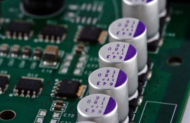
SMT components, also known as Surface Mount Devices (SMDs), are electronic components designed for surface mounting. These components include resistors, capacitors, diodes, transistors, and integrated circuits (ICs). SMDs are significantly smaller than their through-hole counterparts, which allows for higher component density on PCBs and contributes to the miniaturization of electronic devices.
The SMT Assembly Process
The SMT assembly process consists of several key steps that ensure the accurate placement and soldering of components on PCBs:
1. PCB Preparation
Before the assembly begins, the PCB must be prepared. This involves designing the board layout with flat solder pads that will accommodate the SMDs. The solder pads are typically coated with a metal finish such as gold or silver to enhance solderability.
Additionally, PCB preparation may include cleaning processes to remove any contaminants that could affect solder adhesion. The choice of materials for PCBs is also critical; materials like FR-4 (a fiberglass epoxy laminate) are commonly used due to their excellent electrical insulation properties and thermal stability.
2. Solder Paste Printing
The next step is applying solder paste to the solder pads using a stencil. The solder paste is a mixture of metal solder and flux that serves as both an adhesive and a conductor when melted. This paste is critical for creating reliable electrical connections between the SMDs and the PCB.
Precision in this step is vital because too much or too little solder paste can lead to defects such as bridging (where solder connects two pads unintentionally) or insufficient solder joints. Advanced printing techniques such as laser-cut stencils help achieve high accuracy in paste application.
3. Component Placement
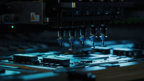
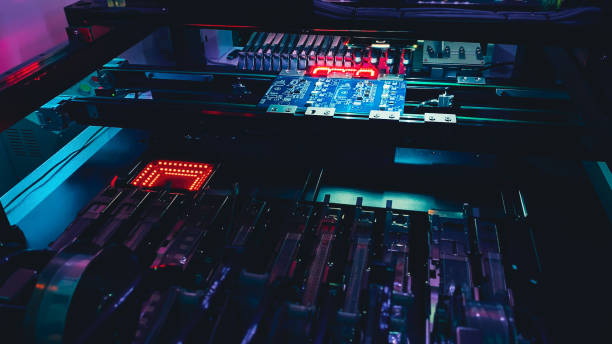
Once the solder paste is applied, a pick-and-place machine accurately positions the SMDs onto the PCB. These machines use vision systems to identify component locations and ensure precise placement. The adhesive properties of the solder paste hold the components in place temporarily until they are permanently soldered.
The speed and accuracy of pick-and-place machines have significantly improved over time, allowing manufacturers to achieve high throughput while maintaining quality standards. Some machines can place thousands of components per hour, making them essential for high-volume production.
4. Reflow Soldering
After placement, the PCB is passed through a reflow oven where it is heated to melt the solder paste. This process creates strong electrical connections between the SMDs and the PCB pads as the solder cools and solidifies.
Reflow ovens operate on a conveyor system that heats the board gradually to avoid thermal shock. The temperature profile is carefully controlled to ensure that all components reach their melting point without overheating sensitive parts. This step is crucial because improper heating can lead to cold joints or damage to components.
5. Inspection and Testing
Finally, automated optical inspection (AOI) systems check for placement accuracy and solder joint quality. Any defects can be identified and corrected before mass production continues.
In addition to AOI, other testing methods such as X-ray inspection may be employed to examine hidden solder joints beneath large components like BGAs (Ball Grid Arrays). Functional testing ensures that each assembled unit operates according to specifications before it leaves the production line.
Advantages of SMT Components
The adoption of SMT components offers numerous advantages over traditional THT methods:
- Space Efficiency: SMT components have a smaller footprint, allowing for more components to fit within a given area on a PCB.
- Higher Component Density: The ability to place components on both sides of a PCB increases overall component density.
- Cost Reduction: Automated assembly processes reduce labor costs and increase production speed.
- Improved Performance: SMT reduces mechanical stress on components due to fewer thermal cycles during soldering.
- Enhanced Reliability: The reduced size and weight of SMT components lead to lower failure rates associated with mechanical and thermal issues.
- Flexibility in Design: Designers can create more intricate circuit layouts without being constrained by component size or lead configuration.
- Lower Inductance: The shorter leads in SMT reduce inductance, which is beneficial for high-frequency applications.

Applications of SMT in Modern Electronics
SMT components are widely used across various industries due to their versatility and efficiency:
- Consumer Electronics: Smartphones, tablets, laptops, televisions, and gaming consoles utilize SMT for compact designs that maximize functionality while minimizing space requirements.
- Automotive Electronics: Advanced driver-assistance systems (ADAS) rely on SMT for reliable performance in space-constrained environments, including safety features like collision detection systems.
- Medical Devices: Miniaturized medical equipment such as pacemakers, diagnostic devices, and wearable health monitors benefit from SMT's ability to integrate complex circuits into small packages.
- Telecommunications: High-frequency communication devices leverage SMT's efficiency for optimal performance in routers, switches, and cellular base stations.
- Industrial Automation: Control systems in industrial settings use SMT for reliable operation under demanding conditions where space is limited but performance cannot be compromised.
- Internet of Things (IoT): As IoT devices proliferate, SMT plays a crucial role in enabling small form factors while providing connectivity features essential for smart applications.
Challenges in SMT Manufacturing
While there are many advantages associated with SMT technology, there are also challenges that manufacturers must address:
- Thermal Management: As devices become more compact with higher component density, managing heat dissipation becomes increasingly important. Effective thermal management solutions must be implemented to prevent overheating.
- Component Handling: The small size of SMDs makes them more susceptible to damage during handling and assembly processes. Careful handling protocols must be established.
- Design Complexity: Designing PCBs for SMT can be more complex than traditional methods due to considerations such as pad sizes, spacing between components, and routing traces effectively without interference.
- Material Compatibility: Selecting compatible materials for both PCBs and components is crucial to ensure reliability over time under various environmental conditions.
Future Trends in SMT Technology
As technology continues to evolve, several trends are shaping the future of SMT:
- Miniaturization: Continued demand for smaller electronic devices will drive further miniaturization of components while maintaining performance standards.
- Advanced Materials: Research into new materials that improve thermal conductivity or reduce weight will enhance the capabilities of SMT assemblies.
- Automation and AI Integration: Increased automation through robotics and artificial intelligence will streamline manufacturing processes further while improving quality control measures.
- 3D Printing Integration: The integration of 3D printing technologies may allow for innovative approaches in producing PCBs with embedded electronics or hybrid designs combining traditional methods with SMT.
Conclusion
Surface Mount Technology has become an integral part of modern electronics manufacturing. By enabling smaller, lighter, and more efficient designs, SMT components have transformed how electronic devices are assembled. The advantages offered by SMT not only enhance performance but also reduce costs, making it a preferred choice for manufacturers worldwide.
As technology continues to advance, it is likely that SMT will play an even more significant role in future innovations within electronics. With ongoing developments addressing challenges such as thermal management and design complexity, we can expect even greater efficiencies in manufacturing processes that will support an ever-expanding range of applications across various industries.

FAQ
1. What is the main difference between SMT and THT?
SMT involves mounting components directly onto the surface of PCBs without drilling holes, while THT requires inserting leads through holes in the board.
2. What types of components are considered SMT?
Common types include resistors, capacitors, diodes, transistors, and integrated circuits (ICs), all designed for surface mounting.
3. How does reflow soldering work?
Reflow soldering involves heating a PCB with applied solder paste in an oven to melt the paste, creating solid electrical connections as it cools.
4. Why are SMT components preferred in modern electronics?
They allow for higher component density, reduced size and weight of devices, lower manufacturing costs, and improved reliability compared to traditional methods.
5. Can both SMT and THT be used on the same PCB?
Yes, it is possible to use both technologies on a single PCB design depending on component requirements.
Citations:
[1] https://www.7pcb.com/blog/what-is-smt
[2] https://en.wikipedia.org/wiki/Surface-mount_technology
[3] https://vicoimaging.com/smd-and-smt-comprehensive-guide/
[4] https://www.mtek.co.uk/frequently-asked-questions-smt-assembly
[5] https://www.wevolver.com/article/smt-process
[6] https://www.pcbx.com/article/20-Common-Q-A-About-SMT-Assembly
[7] https://versae.com/smt-assembly-faq/
[8] https://www.pcbelec.com/pcb-assembly/what-is-a-surface-mount-device
[9] https://www.raypcb.com/smt-components/


