Content Menu
● Introduction
● Understanding Surface Mount Devices
● Common Issues in Surface Mount Device Circuits
>> Solder Bridging
>> Insufficient Solder Joints
>> Tombstoning
>> Cold Solder Joints
>> Component Misalignment
● Troubleshooting Methodology
>> Visual Inspection
>> Testing Components Individually
>> Check Power Supply Stability
>> Thermal Imaging
● Advanced Troubleshooting Techniques
>> Automated Optical Inspection (AOI)
>> X-ray Inspection
>> Rework Techniques
● Conclusion
● FAQ
>> 1. What is solder bridging and how can it be fixed?
>> 2. How to identify and fix cold solder joints?
>> 3. What causes tombstoning in SMDs?
>> 4. How to handle electrical opens in SMT?
>> 5. What is the impact of improper component placement?
Introduction
Surface Mount Technology (SMT) has revolutionized the electronics manufacturing industry by allowing for higher component densities and automated assembly processes. However, with these advancements come a variety of challenges that can affect the performance and reliability of surface mount device (SMD) circuits. This article will explore common issues encountered in SMT circuits, effective troubleshooting methods, and solutions to ensure optimal performance.

Understanding Surface Mount Devices
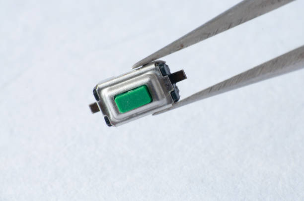
Surface Mount Devices (SMDs) are electronic components that are mounted directly onto the surface of printed circuit boards (PCBs). Unlike traditional through-hole components, SMDs are smaller and can be placed more densely on a PCB, which is crucial for modern compact electronic devices. However, their size and the complexity of the assembly process can lead to various issues that require careful troubleshooting.
Common Issues in Surface Mount Device Circuits
Solder Bridging
Problem: Solder bridging occurs when excess solder forms a connection between two conductors that should not be electrically connected, leading to shorts.
Solution: To mitigate solder bridging, ensure proper stencil design and solder paste application. Adjusting the reflow profile can also help by controlling the heating rates to prevent excessive solder flow.
Insufficient Solder Joints
Problem: Insufficient solder joints can lead to electrical opens where two points that should be connected are not properly soldered.
Solution: This issue often arises from inadequate solder paste application or clogs in the stencil apertures. Regular inspection and maintenance of the solder paste printing process are essential to ensure consistent application.
Tombstoning
Problem: Tombstoning occurs when one side of a two-pin component lifts off its pad during reflow, resembling a tombstone.
Solution: This defect is usually caused by thermal imbalances during reflow. To prevent this, ensure that pad sizes are equal and that components are placed symmetrically relative to thermal profiles.
Cold Solder Joints
Problem: Cold solder joints appear dull and grainy, indicating poor electrical connections that can lead to intermittent failures.
Solution: These joints typically result from inadequate heat during the reflow process. Adjusting the thermal profile to ensure proper melting of the solder is critical.
Component Misalignment
Problem: Misalignment occurs when components are not placed accurately on their pads, which can affect both functionality and manufacturability.
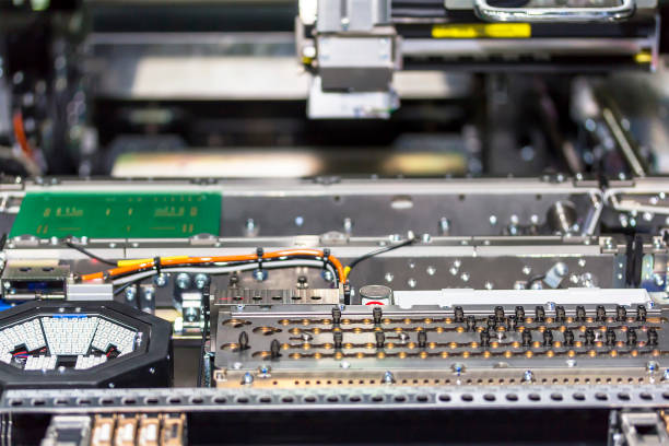
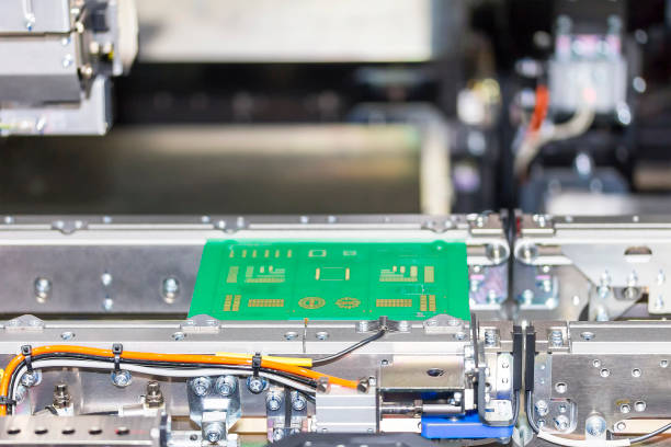
Solution: Use accurate pick-and-place machines with vision systems for precise alignment. Regular calibration and maintenance of these machines can significantly reduce misalignment issues.

Troubleshooting Methodology
Effective troubleshooting in SMT requires a systematic approach:
Visual Inspection
Begin with a thorough visual inspection of the PCB using magnification tools to identify obvious defects such as burnt components, misaligned parts, or cold solder joints.
Testing Components Individually
Use tools like multimeters and oscilloscopes to test individual components for functionality. This step helps isolate faulty components that may be causing circuit failures.
Check Power Supply Stability
Many issues in SMT circuits stem from power supply problems. Measure voltages at various points in the circuit to ensure they meet specifications.
Thermal Imaging
Utilize thermal cameras to detect hotspots on PCBs that may indicate shorts or overheating components, allowing for targeted repairs.
Advanced Troubleshooting Techniques
Automated Optical Inspection (AOI)
Implement AOI systems post-assembly to catch defects early in the production process, reducing rework and improving yield rates.
X-ray Inspection
For complex packages like BGAs (Ball Grid Arrays), X-ray inspection can reveal hidden defects such as insufficient solder joints or voids within the solder connections.
Rework Techniques
Develop skills in reworking techniques such as desoldering faulty components and repairing broken traces using jumper wires or conductive pens.
Conclusion
Understanding common troubleshooting practices in SMT circuits enhances reliability and reduces downtime significantly. By employing systematic inspection methods, utilizing advanced technologies like AOI and X-ray inspection, and maintaining strict quality control throughout the assembly process, manufacturers can effectively address typical concerns encountered in SMT production lines.
In summary, addressing issues such as solder bridging, insufficient joints, tombstoning, cold joints, and misalignment through proactive measures will lead to improved circuit performance and longevity in surface mount device applications.

FAQ
1. What is solder bridging and how can it be fixed?
Solder bridging occurs when excess solder connects two conductors unintentionally, causing shorts. It can be fixed by adjusting stencil designs and ensuring proper paste application during assembly.
2. How to identify and fix cold solder joints?
Cold solder joints appear dull or grainy due to insufficient heat during reflow. They can be identified through visual inspection and fixed by adjusting the thermal profile during reflow processes.
3. What causes tombstoning in SMDs?
Tombstoning is caused by uneven heating during reflow, which leads one side of a component to lift off its pad while the other remains attached. Ensuring symmetrical placement and equal pad sizes can help mitigate this issue.
4. How to handle electrical opens in SMT?
Electrical opens occur when there is insufficient solder or improper contact between leads and pads during reflow. Ensuring adequate paste deposition and inspecting for clogs before assembly can help prevent this issue.
5. What is the impact of improper component placement?
Improper placement affects both performance and manufacturability, leading to potential failures or difficulties during testing and repair processes. Utilizing accurate placement systems is essential for preventing these issues.


