Content Menu
● Understanding Base Plate Thickness in SMT PCB Assembly
>> Key Roles of Base Plate Thickness
● Impacts of Base Plate Thickness on SMT PCB Assembly
>> 1. Warpage and Deformation
>> 2. Solder Joint Quality
>> 3. Component Placement Accuracy
>> 4. Thermal Performance
>> 5. Cost Implications
● Advanced Considerations for Base Plate Thickness in SMT PCB Assembly
>> Impedance Control and Signal Integrity
>> Multilayer PCB Considerations
>> Thermal Management Strategies
>> Flex and Rigid-Flex PCB Considerations
● Emerging Technologies and Their Impact on Base Plate Thickness
>> 5G and High-Frequency Applications
>> Miniaturization Trends
>> Advanced Materials
● Best Practices for Managing Base Plate Thickness in SMT PCB Assembly
● Future Trends in Base Plate Thickness for SMT PCB Assembly
● Conclusion
● Frequently Asked Questions (FAQs)
>> 1. What is the ideal base plate thickness for SMT PCB assembly?
>> 2. How does base plate thickness affect warpage during reflow?
>> 3. Can thicker base plates improve thermal management?
>> 4. What adjustments are needed in stencil design for different base plate thicknesses?
>> 5. Are there cost implications associated with varying base plate thicknesses?
The thickness of the base plate in Surface Mount Technology (SMT) Printed Circuit Board (PCB) assembly is a critical factor influencing the manufacturing process, performance, and reliability of electronic devices. This article explores the various aspects of base plate thickness, its impact on SMT PCB assembly, and best practices for optimizing assembly processes.

Understanding Base Plate Thickness in SMT PCB Assembly
The base plate, or substrate, forms the structural foundation of a PCB. Its thickness can vary depending on the application, ranging from ultra-thin boards used in compact electronics to thicker boards for industrial applications. Typical thicknesses range from 0.4 mm to 3.2 mm, but custom specifications are also common.
Key Roles of Base Plate Thickness
1. Mechanical Stability: Thicker base plates provide greater mechanical support, reducing risks of bending or warping during assembly and operation.
2. Thermal Management: The thickness affects heat dissipation capabilities, which is crucial for high-power applications.
3. Signal Integrity: It influences impedance control and signal propagation in high-frequency PCBs.
4. Manufacturability: Thinner boards may be prone to warping during the SMT process, while thicker boards can pose challenges in drilling and layer alignment.
Impacts of Base Plate Thickness on SMT PCB Assembly
1. Warpage and Deformation
Warpage is a major concern during SMT reflow soldering. Thin PCBs are more likely to warp due to thermal stresses, leading to misalignment of components and soldering defects such as tombstoning or solder bridging. Conversely, thicker PCBs are more resistant to warping but may require higher reflow temperatures, which can stress components.
2. Solder Joint Quality
The base plate thickness directly affects the solder joint height and strength. For example:
- Thicker PCBs may require adjustments in stencil design to ensure sufficient solder paste deposition.
- Uneven warpage in thin PCBs can lead to inconsistent solder joint heights, impacting reliability.
3. Component Placement Accuracy
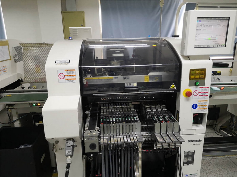
Thin PCBs are more susceptible to vibrations during the pick-and-place process, which can lead to skewed or misaligned components. Proper support fixtures are essential for maintaining placement accuracy.
4. Thermal Performance
Thicker base plates generally offer better heat dissipation but may introduce thermal gradients during reflow soldering. This requires careful profiling of the reflow oven to prevent overheating or underheating specific areas of the PCB.
5. Cost Implications
Thicker PCBs typically cost more due to increased material usage and manufacturing complexity. However, they may reduce long-term costs by improving durability and reducing defect rates.
Advanced Considerations for Base Plate Thickness in SMT PCB Assembly
Impedance Control and Signal Integrity
In high-frequency applications, base plate thickness plays a crucial role in maintaining signal integrity. The thickness affects the characteristic impedance of transmission lines, which is critical for minimizing signal reflections and ensuring proper signal propagation. Engineers must carefully consider the base plate thickness when designing high-speed PCBs to achieve the desired impedance values and maintain signal quality.
Multilayer PCB Considerations
For multilayer PCBs, the overall thickness of the board is a sum of individual layer thicknesses, including the base plate. The complexity increases as more layers are added, requiring precise control over each layer's thickness to maintain the desired overall board thickness. This becomes particularly challenging when dealing with high-density interconnect (HDI) boards, where ultra-thin layers are common.
Thermal Management Strategies
While thicker base plates can improve heat dissipation, they are not always the optimal solution for thermal management. Advanced cooling techniques such as embedded heat sinks, thermal vias, or copper coin technology can be more effective. These methods allow for better thermal performance without significantly increasing the overall board thickness, which is crucial for maintaining the compact form factor of modern electronic devices.

Flex and Rigid-Flex PCB Considerations
Flex and rigid-flex PCBs present unique challenges when it comes to base plate thickness. The flexible portions require extremely thin base materials to achieve the desired flexibility, while the rigid sections may need thicker base plates for stability. Balancing these requirements is crucial for successful SMT assembly of flex and rigid-flex PCBs.
Emerging Technologies and Their Impact on Base Plate Thickness
5G and High-Frequency Applications
The advent of 5G technology has pushed the boundaries of PCB design, requiring even more precise control over base plate thickness. High-frequency signals used in 5G applications are particularly sensitive to variations in PCB thickness, making it crucial to maintain tight tolerances during manufacturing.
Miniaturization Trends
As electronic devices continue to shrink, there's an increasing demand for ultra-thin PCBs. This trend challenges manufacturers to develop new materials and processes that can maintain the necessary mechanical and electrical properties at ever-decreasing thicknesses.
Advanced Materials
New PCB materials are being developed to address the challenges posed by varying base plate thicknesses. These include high-Tg (glass transition temperature) materials that resist warping at high temperatures, and low-loss materials that improve signal integrity in high-frequency applications.
Best Practices for Managing Base Plate Thickness in SMT PCB Assembly
1. Material Selection: Choose materials with low thermal expansion coefficients to minimize warpage during reflow. Consider advanced composites for applications requiring specific thermal or electrical properties.
2. Design Optimization: Incorporate Design for Manufacturing (DFM) principles to balance thickness with performance requirements. Use simulation tools to predict thermal and mechanical behavior before production.
3. Reflow Profiling: Use precise thermal profiling for consistent soldering results across varying board thicknesses. Implement zone-specific temperature control in reflow ovens to address thermal gradients in thicker boards.
4. Fixture Support: Employ custom fixtures or carriers for thin PCBs to enhance mechanical stability during assembly. Consider using vacuum tables or magnetic fixtures for ultra-thin boards.
5. Stencil Design: Adjust stencil thickness and aperture size based on the PCB's base plate thickness to ensure optimal solder paste deposition. Use step stencils for boards with varying component heights.
6. Component Selection: Choose components that are compatible with the selected base plate thickness. Consider using low-profile components for thin PCBs to maintain overall device thickness.
7. Quality Control: Implement rigorous inspection processes, including automated optical inspection (AOI) and X-ray inspection, to detect defects related to base plate thickness variations.
8. Process Documentation: Maintain detailed documentation of assembly processes for different base plate thicknesses to ensure consistency and facilitate continuous improvement.
Future Trends in Base Plate Thickness for SMT PCB Assembly
As technology continues to evolve, we can expect to see further innovations in PCB manufacturing that will impact base plate thickness considerations:
- Additive Manufacturing: 3D printing technologies may enable more precise control over PCB thickness and allow for variable thickness within a single board.
- Embedded Components: The trend towards embedding components within the PCB layers may lead to new approaches in managing overall board thickness.
- AI-Driven Design: Artificial intelligence and machine learning algorithms may optimize PCB designs for specific thickness requirements, balancing performance, manufacturability, and cost.
Conclusion
Base plate thickness plays a pivotal role in determining the success of SMT PCB assembly processes. While thinner boards enable compact designs, they require careful handling to avoid defects like warpage and misalignment. Thicker boards provide mechanical robustness but come with their own set of challenges, such as increased costs and thermal management complexities. By understanding these trade-offs and implementing best practices, manufacturers can optimize their SMT processes for improved reliability and performance.
As the electronics industry continues to push the boundaries of miniaturization and performance, the importance of precise control over base plate thickness in SMT PCB assembly will only grow. Staying informed about emerging technologies and continuously refining manufacturing processes will be key to meeting the evolving demands of modern electronic devices.

Frequently Asked Questions (FAQs)
1. What is the ideal base plate thickness for SMT PCB assembly?
The ideal thickness depends on the application:
- Compact devices: 0.4–1 mm (thin boards).
- Industrial applications: 1.6–3.2 mm (thicker boards).
Consider factors like mechanical strength, thermal performance, and manufacturability when choosing.
2. How does base plate thickness affect warpage during reflow?
Thin PCBs are more prone to warping due to thermal expansion during reflow soldering. Using materials with low thermal expansion coefficients and proper support fixtures can mitigate this issue.
3. Can thicker base plates improve thermal management?
Yes, thicker base plates enhance heat dissipation but may introduce challenges like uneven heating during reflow soldering.
4. What adjustments are needed in stencil design for different base plate thicknesses?
For thicker PCBs, increase stencil aperture size or use thicker stencils to ensure adequate solder paste deposition. For thinner boards, precise control over paste volume is critical to avoid defects.
5. Are there cost implications associated with varying base plate thicknesses?
Yes, thicker PCBs generally cost more due to increased material usage and processing complexity but may reduce defect rates and improve durability over time.


