Content Menu
● Introduction
● Understanding SMT Components
>> Common Causes of Failure in SMT Components
● Identifying Blown SMT Components
>> Visual Inspection Techniques
>> Using Multimeters and Other Diagnostic Tools
>> Common Signs of Blown Components
● Step-by-Step Diagnosis Process
● Tools and Techniques for Diagnosis
>> Essential Tools
>> Advanced Techniques
● Preventive Measures
● Conclusion
● FAQ
>> 1. What are the common signs of a blown SMT component?
>> 2. How can I safely diagnose a blown SMT component?
>> 3. What tools are essential for diagnosing SMT components?
>> 4. Can blown SMT components be repaired?
>> 5. How often should PCBs be inspected for blown components?
● Citations:
Introduction
Surface Mount Technology (SMT) components are crucial in modern printed circuit boards (PCBs), providing compact and efficient solutions for electronic assemblies. Diagnosing blown SMT components is essential for maintaining the functionality and reliability of electronic devices. This article delves into the methods and tools used to identify and diagnose faulty SMT components on a PCB, ensuring that your electronics operate smoothly.

Understanding SMT Components
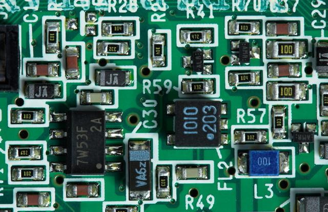
SMT components are electronic devices mounted directly onto the surface of a PCB. They come in various forms, including resistors, capacitors, diodes, and integrated circuits. The compact nature of SMT allows for higher component density, which is vital for modern electronics where space is at a premium.
Common Causes of Failure in SMT Components
Several factors can lead to the failure of SMT components:
- Electrical Overstress: Excessive voltage or current can damage components. This often occurs due to incorrect power supply settings or accidental short circuits.
- Thermal Stress: Overheating due to inadequate heat dissipation or prolonged high temperatures can cause components to fail. Poor thermal management can exacerbate this issue, leading to thermal runaway in sensitive devices.
- Manufacturing Defects: Poor soldering techniques or defective components can lead to premature failures. Issues such as cold solder joints or improper component orientation during assembly can significantly impact reliability.
- Environmental Factors: Exposure to moisture, dust, or corrosive substances can also lead to component failure over time. Humidity can cause oxidation and corrosion, while dust accumulation can trap heat.
Identifying Blown SMT Components
Visual Inspection Techniques
The first step in diagnosing blown SMT components involves visual inspection. Technicians should look for:
- Burn Marks: Discoloration on the PCB or around the component indicates overheating. This may appear as dark spots or charred areas.
- Bulging Components: Any component that appears swollen or misshapen is likely damaged. Capacitors are particularly prone to this type of failure.
- Hot Spots: Areas on the PCB that feel significantly warmer than others during operation may indicate a failing component. These hot spots can often be identified by carefully touching the board with a fingertip (ensuring safety precautions).
- Cracked or Broken Leads: Inspect for any physical damage to leads or solder joints that may indicate stress or fatigue.
Using Multimeters and Other Diagnostic Tools
A multimeter is an indispensable tool for diagnosing SMT components. It can measure voltage, current, and resistance, helping to identify open or short circuits. Here's how to use it effectively:
1. Power Off the PCB: Always ensure the PCB is powered off before testing to prevent further damage and ensure safety.
2. Test Individual Components: Measure resistance across resistors and capacitors. A reading significantly different from expected values indicates a problem. For example, a resistor showing zero ohms may be shorted.
3. Check for Continuity: Use the continuity setting to test connections between points on the board. This helps identify broken traces or faulty connections.
4. Voltage Testing: While powered on, measure voltage at various points to ensure components are receiving proper power. Compare these readings with expected values from the circuit schematic.
5. Capacitance Testing: For capacitors, use a multimeter with capacitance measurement capabilities to check if they are within tolerance levels.
Common Signs of Blown Components
Blown SMT components often exhibit distinct physical damage:
- Burn Marks: These are clear indicators of overheating and failure.
- Bulging: Components that appear swollen are likely compromised; this is especially true for electrolytic capacitors.
- Discoloration: Changes in color can indicate thermal damage; this might also affect surrounding areas on the PCB.
- Solder Joint Issues: Look for cracks or dull solder joints which may indicate poor connections due to thermal cycling.

Step-by-Step Diagnosis Process
To effectively diagnose blown SMT components, follow this structured approach:
1. Power Off the PCB: Always start by disconnecting power to prevent shock or further damage.
2. Conduct a Visual Inspection: Look for obvious signs of damage such as burn marks, bulging components, and cracked leads.
3. Use a Multimeter: Test individual components for continuity and resistance to identify faulty ones.
4. Signal Probing: If available, use signal probes to trace signals through the circuit and identify where failures occur. This technique is particularly useful for complex circuits where multiple signals interact.
5. Compare with a Functional Board: If possible, compare the faulty board with a known good board to identify discrepancies in component behavior or connections.
6. Thermal Imaging: Utilize thermal imaging cameras to detect hotspots on the PCB during operation, which can help pinpoint failing components without direct contact.
7. Functional Testing: After replacing suspected faulty components, conduct functional tests on the entire assembly to ensure everything operates correctly under load conditions.
Tools and Techniques for Diagnosis
Essential Tools
- Multimeter: For measuring electrical properties like voltage, current, and resistance.
- Oscilloscope: Useful for observing waveforms and diagnosing timing issues in signals.
- Signal Probes: Help trace signal paths on the PCB without direct contact with sensitive areas.
- Thermal Camera: Allows technicians to visualize temperature distribution across the PCB during operation.
- Soldering Iron and Desoldering Tools: Essential for replacing damaged components safely and effectively.
Advanced Techniques
For more complex diagnoses, consider using advanced techniques:
- Automatic Optical Inspection (AOI): This technology uses cameras to scan PCBs for defects automatically, identifying issues like misaligned components or solder defects that may not be visible through manual inspection.
- X-ray Inspection: Allows for examination of hidden solder joints and internal structures without disassembling the board; particularly useful for BGA (Ball Grid Array) packages where solder joints are not visible from above.
- In-Circuit Testing (ICT): This method tests individual components while they are still mounted on the PCB using specialized equipment designed to apply test signals through test probes connected directly to each pin of every component.
Preventive Measures
Preventive measures can significantly reduce the likelihood of blown SMT components:
- Proper Design Considerations: Ensure that circuit designs account for potential thermal issues by incorporating adequate heat sinks and thermal vias where necessary.
- Quality Component Selection: Choose high-quality components rated for higher voltages and temperatures than those they will encounter during operation.
- Regular Maintenance Checks: Implement routine inspections of PCBs in critical applications to catch potential issues before they lead to component failure.
- Environmental Control: Maintain suitable environmental conditions such as humidity control and dust-free environments during storage and operation.
Conclusion
Diagnosing blown SMT components is a critical skill for maintaining the performance and reliability of electronic devices. By employing appropriate tools and systematic techniques, technicians can effectively identify and replace faulty components, ensuring longevity and optimal operation of PCBs. Regular inspections and maintenance practices are essential in preventing failures in electronic systems. Understanding common causes of failure and implementing preventive measures will further enhance the reliability of your electronic assemblies.

FAQ
1. What are the common signs of a blown SMT component?
Common signs include burn marks, bulging, hot spots on the PCB, discoloration around solder joints, and cracked leads on components.
2. How can I safely diagnose a blown SMT component?
Ensure power is off before testing; use appropriate tools like multimeters; follow safety guidelines throughout diagnosis processes; avoid touching live circuits directly.
3. What tools are essential for diagnosing SMT components?
Essential tools include multimeters for electrical measurements, oscilloscopes for waveform analysis, signal probes for tracing signals without contact, thermal cameras for hotspot detection, and soldering tools for component replacement.
4. Can blown SMT components be repaired?
Some components can be replaced; however, repair depends on the extent of damage sustained by the component—most often replacement is recommended rather than attempting repairs due to reliability concerns post-repair.
5. How often should PCBs be inspected for blown components?
Regular inspections are recommended after any malfunction occurs or periodically based on usage patterns—especially in critical applications—to ensure optimal performance over time.
Citations:
[1] https://www.sunstreamglobal.com/a-comprehensive-guide-on-finding-a-faulty-components-in-pcb/
[2] https://www.candorind.com/blog/circuit-board-troubleshooting-techniques/
[3] https://www.vse.com/blog/2022/03/15/8-common-smt-placement-issues-and-solutions/
[4] https://resources.pcb.cadence.com/blog/2024-how-to-find-faulty-components-on-a-pcb-a-guide
[5] https://forum.allaboutcircuits.com/threads/identifying-blown-components.93532/


