Content Menu
● Understanding Surface Mount Devices
● The Importance of Surface Mount Technology
● The Soldering Process for Surface Mount Devices
>> 1. Solder Paste Application
>> 2. Component Placement
>> 3. Reflow Soldering
>> 4. Inspection
>> 5. Rework and Repair
● Tools Required for Soldering SMDs
● Common Techniques for Hand-Soldering SMDs
>> 1. Using Solder Paste and Hot Air
>> 2. Drag Soldering Method
● Challenges in Surface Mount Soldering
● Conclusion
● FAQ
>> 1. What is a surface mount device (SMD)?
>> 2. What tools do I need for hand-soldering SMDs?
>> 3. How does reflow soldering work?
>> 4. What are common issues when working with SMDs?
>> 5. Can I mix SMT with through-hole technology?
Surface mount technology (SMT) has revolutionized the electronics manufacturing industry by allowing for the efficient assembly of electronic components onto printed circuit boards (PCBs). This article will explore the process of soldering and installing surface mount devices (SMDs) on PCBs, detailing the techniques, tools, and considerations involved in this critical aspect of modern electronics.

Understanding Surface Mount Devices
Surface Mount Device Definition
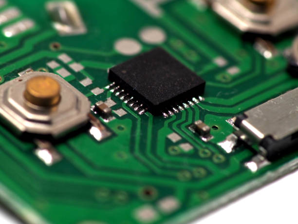
A surface-mounted device (SMD) is an electronic component that is mounted directly onto the surface of a PCB. Unlike traditional through-hole components, which require holes to be drilled into the board, SMDs are designed to be soldered directly onto pads on the PCB's surface. This method allows for a more compact design and facilitates automated assembly processes, leading to reduced manufacturing costs and improved reliability.
The Importance of Surface Mount Technology
Surface mount technology emerged in the 1980s as a response to the growing demand for smaller, more efficient electronic devices. The advantages of SMT include:
- Reduced Size: SMDs are generally smaller than their through-hole counterparts, allowing for higher component density on PCBs.
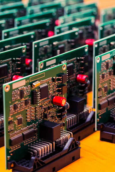
- Automated Assembly: SMT processes can be highly automated, reducing labor costs and increasing production rates.
- Improved Performance: The shorter electrical paths in SMDs can lead to better performance characteristics in high-frequency applications.
The Soldering Process for Surface Mount Devices
The soldering process for SMDs typically involves several key steps:
1. Solder Paste Application
Before components can be placed on the PCB, solder paste must be applied to the pads where the components will be soldered. This is usually done using one of two methods:
- Stencil Printing: A stencil with openings corresponding to the pads is placed over the PCB. Solder paste is then spread across the stencil, filling the openings with paste.
- Jet Dispensing: In this method, a machine dispenses precise amounts of solder paste directly onto the pads without using a stencil.
2. Component Placement
Once the solder paste is applied, surface mount components are placed onto the PCB using a pick-and-place machine. This machine uses a vacuum nozzle to pick up components from feeders and accurately place them onto the solder paste deposits.
3. Reflow Soldering
After placement, the PCB is heated in a reflow oven. This process melts the solder paste, creating strong electrical and mechanical connections between the SMDs and the PCB pads. The heating profile must be carefully controlled to avoid damaging sensitive components.
4. Inspection
Once reflow soldering is complete, automated optical inspection (AOI) systems check for defects such as misaligned components or insufficient solder joints. This step is crucial for ensuring high-quality assemblies.
5. Rework and Repair
If defects are found during inspection, rework may be necessary. This involves reheating specific areas to remove faulty components and reapplying solder as needed.

Tools Required for Soldering SMDs
To effectively solder surface mount devices, several tools are essential:
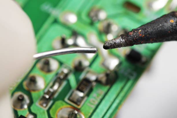
- Soldering Iron: A fine-tipped soldering iron allows for precise application of heat.
- Solder Paste: A mixture of solder alloy and flux that facilitates good electrical connections.
- Tweezers: Precision tweezers are necessary for handling small components during placement.
- Magnification Tools: A magnifying glass or microscope can help ensure accurate placement and inspection of small parts.
- Flux Pen: Flux improves solder flow and helps prevent oxidation during soldering.
Common Techniques for Hand-Soldering SMDs
While automated processes dominate industrial production, hobbyists and engineers often need to hand-solder SMDs. Here are some effective techniques:
1. Using Solder Paste and Hot Air
For small components like resistors or capacitors:
1. Apply a small amount of solder paste to each pad.
2. Place the component on top of the paste.
3. Use a hot air rework station to gently heat the area until the solder melts.
2. Drag Soldering Method
For multi-pin devices like integrated circuits:
1. Apply flux to all pins.
2. Place a small amount of solder on one pin.
3. Heat that pin while dragging the soldering iron along the row of pins to create connections.
This method can be very effective but requires practice to avoid bridging between pins.
Challenges in Surface Mount Soldering
Despite its advantages, surface mount soldering comes with challenges:
- Alignment Issues: Misalignment during placement can lead to poor connections or short circuits.
- Thermal Sensitivity: Many SMDs are sensitive to heat; excessive temperatures can damage them.
- Cleaning Residue: After soldering, cleaning flux residue from PCBs is essential to prevent corrosion or electrical issues.
Conclusion
Surface mount technology has become an integral part of modern electronics manufacturing due to its efficiency and ability to produce compact designs. Understanding how to properly solder and install surface mount devices on PCBs is crucial for anyone involved in electronics assembly—whether professionally or as a hobbyist. With advancements in automation and techniques for hand-soldering, mastering these skills will enable you to create reliable electronic devices that meet today's demanding standards.

FAQ
1. What is a surface mount device (SMD)?
A surface mount device (SMD) is an electronic component designed to be mounted directly onto the surface of a printed circuit board (PCB), eliminating the need for drilling holes as required by traditional through-hole components.
2. What tools do I need for hand-soldering SMDs?
Essential tools include a fine-tipped soldering iron, tweezers, solder paste or wire, flux pens, magnification tools, and sometimes hot air rework stations for heating components evenly.
3. How does reflow soldering work?
Reflow soldering involves applying solder paste to PCB pads, placing components on top, and then heating them in an oven where the paste melts into solid connections between components and pads as it cools down.
4. What are common issues when working with SMDs?
Common issues include misalignment during placement, thermal sensitivity leading to component damage from excessive heat, and ensuring clean connections without excess residue from flux or solder.
5. Can I mix SMT with through-hole technology?
Yes! Many PCBs use both SMT and through-hole technologies simultaneously; however, careful planning is needed during assembly processes to ensure compatibility between both types of components.


